- Bearings
 Vertical Bearings
- AV Series
AV
LV SeriesLV
MV SeriesMV
V SeriesV
 Horizontal Bearings
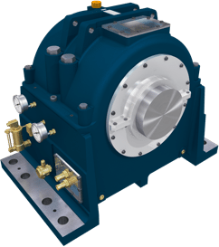
- HD Series
HD
IH SeriesIH
 Tilting Pad Bearings
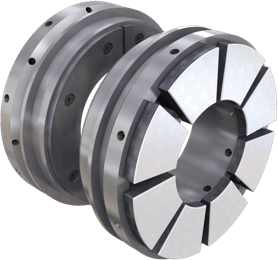
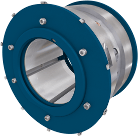 Journal Bearings
- Journal Pad Units
Journal
 Thrust Bearings
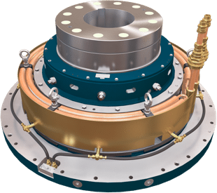
- SE Series
SE
Omega EqualisedOmega
OmegaOmega
 Marine Bearings
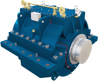
- Marine Gearbox InternalsHome > Naval Thrust Bearings
Naval Thrust Bearings
J E L Simmons and N Henderson, Michell Bearings, UKSynopsis
Marine thrust bearings have been developed for naval use from the earliest days of screw propulsion, through multicollar thrust blocks to the present generations of tilting pad bearings. Following the introduction of the Michell thrust bearing to marine applications in the years around the First World War, there was a long period of relative stability in bearing technology. During this time there were few design changes of major interest. In the past 20 years, however, a much wider range of choices have become available. Bearing casings, although retaining similar internal arrangements, are now designed to suit different shipboard machinery layouts. The increasing requirement for submersible vessels to operate continuously at depth at very slow speeds, has led to methods for enhancing the load carrying capacity of bearings in a situation which is unfavourable for hydrodynamic lubrication. Lubrication systems themselves have been developed with self-contained thrust bearings becoming a realistic choice in some cases. Possible future bearing developments include the use of active magnetic bearings to absorb at least part of normal thrust loadings.
Historical
The nineteenth century pioneers of screw propulsion quickly discovered that there must be adequate provision within the hull of a vessel to absorb the reaction of the propeller thrust. John Bourne’s book on the screw propeller, published in 1852, gives considerable attention to various thrust devices. Figure 1 shows the arrangements in the single screw vessel, HMS Ajax. To quote the author: ‘The thrust of the screw is received upon a cast iron upright applied to the end of the shaft for that purpose’. Notice that the astern thrust is taken at the end of the shaft aft of the propeller, where best practice was to fit a disc with lignum vitae segments. Such simple bearings on the ends of propeller shafts were soon found to be inadequate and were replaced by multi-collar thrust blocks, in either enclosed or open horseshoe form as shown in Fig 2. These multi-collar systems formed the new standard until the advent of single collar, tilting pad thrust blocks during the First World War.
The horseshoe type of multi-collar thrust with provision for independent adjustment of the shoes was a fine piece of engineering. However as speeds and powers advanced, the multi-collar thrust found it increasingly difficult to accommodate the heavier loads it was called upon to bear. The solution was to provide more and more load bearing surface until, in the case of at least one merchant liner, no less than 22 collars were required in the design. As we now know the conditions for hydrodynamic lubrication were far from ideal and continual adjustment was necessary to ensure an even distribution ofload between the collars. Power losses were considerable, with enormous amounts of heat being generated at the bearings. Continuous wear of the bearing elements ensured that frequent replacement was essential.
The introduction to marine use, at about the turn of the century, of the direct drive steam turbine temporarily eased the situation. In these turbines practically all the thrust was balanced by steam pressure on a dummy piston. However with the later development of geared turbine propulsion systems around 1912, thrust block problems re-appeared in aggravated form. According to J H Gibson, marine engineers of the day were ‘at their wits’ end’ for a solution until it was realised that the remedy was at hand in the form of the single collar, tilting pad thrust bearing which we know today.
ACCESS FULL PAPERMichell Bearings
Waldridge Way,
Simonside East Industrial Park,
South Shields,
NE34 9PZ.© Michell Bearings.
Registered Office Address: 11 Glasshouse Street, St Peter's, Newcastle upon Tyne. NE6 1BS. Company registered in England and Wales no. 9390648
 PTFE Bearings